
Thank you! Your comment has been submitted successfully. You should be able to view your question/comment here within a few days.
Error submitting comment. Please try again momentarily.


Features:
California residents: click here
Videos are provided as a guide only. Refer to manufacturer installation instructions and specs for complete information.
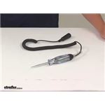
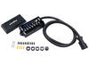
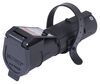
Hi, they're hard workers! Today we're going to be taking a look at Performance Tool's LCD circuit tester. To give you an idea of how your circuit tester works, it has LEDs in here that'll light up when both power and ground is present. You'll have to clip your probe onto either power or ground. The, the clip end here, we've got that attached to the ground side of our battery. And then with the probe end, instead of the clip side, you'll touch this to your other circuit. And if there is the opposite there it'll light up.
So currently you've got ground on the clip side and our probe, or touching on the positive of our battery post and it lights up red. It also gives us a voltage reading on there, raking in about 12 and a half volts. Now we could swap this and hook it up the other direction. So we're hooking our clip onto positive, and then we're going to take our probe and touch it to ground, and it also lights up. But you will notice now that it's lit up green, letting you know that your probe side is touching on ground and you have power present on your clip side.
You'll also get a voltage reading there. And that's really nice that you get a voltage reading there, because if you have any drop across your circuit, you can help detect that as well. So you can kind of check out the integrity of your circuit while doing this. It's kind of a special thing here. Most of your test lights will just have a light on it.
It's really nice. And you've got that volt meter on there as well to get additional information. For example, currently now we're reading about 12 and a half volts, but if I was checking this further on down the circuit, and if we had some corrosion in that circuit, I may only read 12.1 volts further on down that circuit. And I know, Hey, the voltage has dropped from what it is here at the battery by a few tenths of a volt down there. Maybe I should look for a little bit of corrosion or a bad connection at that point.
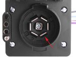
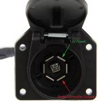
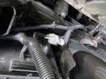
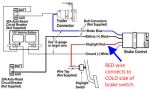
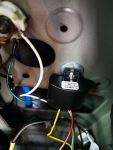
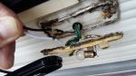
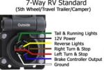
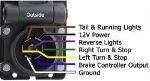
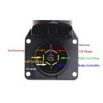
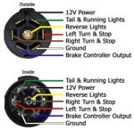
And it may even drop even lower. You may only have like 10 or 11 volts and if you're checking it like that, then there's a good chance that you're finding, Hey, this is probably why I'm finding where my issue is. My item wasn't working. I was checking my circuits along the way, and I see a drop in voltage that's excessive, check your circuits there. So we're gonna go ahead and go through some examples of common uses of this and some, little bit more in depth tests that you can perform with a test light. Often people will use these to test the circuits at the back of their vehicle, and they usually do this when they plug up to your trailer and you find like, Hey, I don't have taillights or I'm missing a turn signal or something like that. Well, rather than immediately digging in and trying to fix some wires, let's figure out, Hey, where's the issue at is the issue on my vehicle side or is the issue with my trailer. That's where I like to start. So I've gone ahead and turned on the hazard lights in the vehicle, as well as the tail lights. And that should activate all of our signals. So we're going to take the clip here. We're gonna hook this on ground, which is the exposed stud there, so just flipping that on there, kind of putting the rubber boot off to the side here a little bit to help keep me from touching it. And now we're just gonna check our circuits. So here, we've got 12 volts here at the back. So we know that our taillight circuits working, and we've got a flashing signal there giving us our 12 volts so we know that that's working. And if we look at here, the color of the wire coming in, that's yellow, so that's gonna be our left turn signal. And then our right turn signal is the green wire. When we checked this one as well, we'd get our light lighting up and giving us our 12 volts. So we know that our vehicle side here is working properly. And this will also work when testing your six and seven way connectors as well. You just need to pay attention to what the circuits are. So for the four-pole ones, we we're able to turn on tail lights and hazards to get all these operational. With a seven way, you'll need a brake controller plugged in and somebody operating the output of it in order to be able to test that circuit, your auxiliary circuit should normally just have power on it all the time, but sometimes you have to start the vehicle to get the auxiliary circuit to come on. So just pay attention to those. So that way you know that you're getting the output back to your connector when you're checking, just verify that your vehicle has that particular output. In this instance, if we had an issue with our trailer though, we know that our vehicle's okay, so we can go ahead and button up this side. We don't need to diagnose anything over here. We would then turn to our trailer and try to figure out, okay, why, why is that signal not working So then we would do that from there. So here, we've got a scenario for you where we're going to show you a short to ground and how to diagnose it. Currently, I've got a scenario set up, so our board here, this is the load for our device. It's going off right now. And this just normally comes on when you put your vehicle in reverse. So let's say in our scenario, we put our vehicle in reverse, but instead of this, coming on, nothing happened because this was what a short to ground would be like, if there was a bare spot on your wire, it would spark a little bit. And what would eventually happen, it was over, it would overload the circuit and then it would pop your fuse. And if we take a look here, we can see that the fuse has blown. It's now open. So this was a temporary thing that we just put in there in place. But if you've got a short to ground in your trailer, it's likely always gonna be grounded out like that. So let's just go ahead and set that scenario up. So now we're in the current faulted state where we had started where the board was working, was the proper fixed state. We simulated a short to ground. So we're just gonna put this short to ground back so I'm stuffing that there. I'm just stuffing this in here just for simulation purposes. So now what's going to happen next is you go, oh, I got a blown fuse. Okay. Well, my fuse is blown. I'll just put another fuse in. And when you go to put another fuse in, you got to pull it back into reverse or operate, whatever accessory you're planning on operating, and it just pops the fuse again. Oh no. Well now, you know, you've got a real problem you gotta solve. Your test light can be a real wonder in these scenarios cause we can take that fuse out of there, Instead of wasting a bunch of fuses, what we can do is we can complete the circuit with our test light. And normally when you're doing this, you're probably gonna have to take a, a paper clip or something like that to clip into the other ends. And you can poke it down in there. So I'm gonna grab one of those real quick so we can mock that up. So now what we've done is we've taken our test light and we put it in place where the fuse used to be. The probe is in one prong, and then we used a paper clip and clipped it onto the clip side of the other side of the test light and put that in the other prong. And what you'll see there is that our test light has lit up. So what you'll want to check now is where, we know that this light's only gonna light up. if we've got a complete circuit that has a path all the way from power, all the way to ground, and then it'll light that light. So at this point you can put it in the particular state in which you're trying to activate, whatever it be, a light or whatever you're putting it in reverse to activate a light, go ahead and do that. We can see that's lit up. And now you would just start disconnecting circuits until you figured out an isolated where the short was. One of the things I like to do first, if it's easy to get to, is to take away the ground at the very end of the circuit, because our test light doesn't take very much current to amp, to light up. So if you think it's like a bulb or something, it can actually go through the bulb, so let's make sure that particularly at the ground at the very end of the circuit, So this is the load at the end. This is normally like a brake light bulb or something. You have your power that goes to the bulb or whatever your load is, and then the other side just goes right to ground. Well, if we remove this ground here at the end, what should happen is your test lights should turn out if there's no shorts, but if you look here, our test light's still lit up. That means that there's a path to ground still somewhere present. So you would work your way down the line to the next easiest connection point that you get to, and you would disconnect it there. If the test light turns off, then you know, okay, my short is between the point that I just disconnected there, and then a point further towards the back of the vehicle, back closer to the battery. If you just keep disconnecting circuits and the lights still light up, it is still lit up, then you know that you need to keep working your way towards the battery to find that issue. After I disconnect the one at the very back, what I usually do next is I'll disconnect the one here at the very front, and that way, I've eliminated between those two connectors and I can start finding that point. So we know our short to ground's here cause We did it here in this particular test scenario. But if we see if we disconnect this circuit there, we have no more test light turned on, cause it's no longer shorted to ground. So that can be a really useful test item to find short to ground without popping a bunch of fuses. Cause if you want to get power in the circuit to check for power, each time you'd have to put that fuse in there. And it probably end up blowing that fuse because of the current state it was in. But we can use our test light to get current through there and check it. Next we're going to show you guys how to perform a voltage drop test. And this is one of my favorite tests for finding difficult issues that can arise with circuits. Cause you could have a circuit that's completed, but still has high resistance or issues with it that can cause strange conditions to occur. So first thing we want to do is we're going to be using the volt meter portion of our test light now to do these tests. So whenever you're doing a voltage drop test, the first thing you want to do as a baseline test. We want to see what the voltage is at the battery. So we've got 12.4 volts right at our battery. We've got this lead on negative than on positive 12.4. We're going to use our test circuit once again. And I want to show you guys something neat. The circuit's complete, all that it needs ground to hook on, and then I'll turn on our board. This board does have a delay in it before it begins to activate the beeping. So we are going to get a little bit of time before it's going to go off on us there. But I wanted to show you guys that while we had 12 volts here at the battery, we check here at the ground connection where it's not disconnect, where it's not connected to ground. It's currently disconnected. Look at this guys. You got about 3.1 Volts there. So we still have some voltage that is present there. And in most cases, you're going to read very close to battery voltage here, unless the resistance gets too high. If we go ahead and clip this on ground, whenever you're checking like a light bulb or any kind of circuit, when you're checking your voltage drop, that can tell you the conditions of your circuit. So we're gonna complete the circuit by clipping this on. That'll complete our circuit here. So now if we check, this is on the ground side here, nothing. It doesn't even light up at all. Because all of our voltage should drop across our load. It should drop completely across here. If you still have voltage present on the other side, that typically indicates that you have a poor connection in here somewhere. I'm gonna go ahead and disconnect it to turn that off. But that usually indicates you've got a poor connection somewhere in here, because there was still some voltage present on the other side of your load. That means that there's corrosion or a bad connection. Maybe you got like two wires are barely touching here. That poor connection there, that high resistance, is actually consuming some of that voltage in order for it to get across that, to get to ground. And that can cause your lights to light up very dimly. If it's a computer module, sometimes it can cause it to wig out to where it does very unexpected things. So by doing your voltage drop test, that's one of my favorite ones to be able to narrow down those issues. And we're going to just run down this circuit here. So we're now at the battery, when we clip on here, we had about 12, four, and it's normal over the length of wire to see about a 10th of a volt drop. So we've got it right here at the battery, 12 three, we're gonna go right just the other side of our circuit protection. And we're right at about 12, 4, 12, 3. We haven't dropped any voltage yet. And then we heard up here to our tester but we can't quite get in there. 12 four still good there. And then we go right onto the other side here while it's activating and we get absolutely nothing. It's completely dropped across the circuit. You always want to see that. If you see something like, maybe you see like 10.4, more than likely, this thing's probably just dropping a little bit of voltage. You've actually really got a major issue on here on the ground side. The more voltage you have on the ground side of the circuit, past the load, the more issue, you know, you've got right here. The other thing we we're checking when we we're checking voltage drop there, we saw that it was nearly 12 four all the way up to our load. Let's say right here at the load, at the light bulb of whatever your load is, you're only measuring maybe like six volts. And of course your lights probably not gonna work, whatever here's probably not working properly. You know, between this point here and the battery up here, you had six volts that has dropped across that circuit. So you need to check the wiring between this point and that point to figure out why that voltage dropped. And again, it's typically going to be caused by a poor connection or heavy corrosion in that circuit. And that completes our look at Performance Tool's LCD circuit tester..


Used it twice it fried would not recommend. I bought the tester for general trailer repair for testing lighting circuits and all around diagnostics the one time that it did work it was nice to see the voltages but I just went back to my regular test light. Nothing like having a tool in your box that is garbage and not dependable. Buyer beware.
This is an awesome product at a great price. Elsewhere online it was $100 so it was a large savings You can check ground just like a regular
trouble light but it light up green and you know how strong your ground is.Then you can check power supply then it lights red for power and lets you know the volts. I have tested my remote battery to find out it was weak it was below 3 new one tested 3.1 .I work in the auto field so it will be used to check batteries, charging systems, light sockets,window switches, ect. I love this tester I wont have to break out my ohm meter near as much.The tester appears to be very well built time will tell.For around $20 everyone should own one.
These guys make that online big box store look like a minor league player. The shipping was fast, the product is great and works well. I will be ordering two more this week as everyone who borrowed mine loved the product. I already sold one to co-workers diagnosing electrical problems. The 48 volt capability makes this one tool capable of diagnosing weak batteries in parrallel and series wiring, measuring solar panel output, and diagnosing voltage draw a breeze.
Excellent product. Just what is needed for all the new electronics systems. Computer safe, test circuits without fear of damaging equipment. The addition of the digital voltage readout is a big plus when testing and trouble shooting. Bought two, will order a third for the boat emergency tool kit. Invaluable tool for those pesky electrical gremlins.
Great product at a great price. It sure came in handy. Thank You.
A very convenient tool. Easy to use.

Bauers H.

4/2/2022
Were a shop that specializes in hitch installs and this absolutely helps a ton in diagnosing wiring and testing for shorts in trailer wiring, the volt meter is unique to this brand and we have nearly 7 on hand because of that.
I received the item way earlier then expected and it works exactly as said and exactly as I need it to. Very high quality great for quick electronic diagnosis.
Works great
Great product work well
great item, fast delivery, just what I ordered. Thank You
good product at affordable price,
Great product and excellent service


Do you have a question about this Electrical Tool?
Info for this part was:
At etrailer we provide the best information available about the products we sell. We take the quality of our information seriously so that you can get the right part the first time. Let us know if anything is missing or if you have any questions.


Paul P.
6/14/2021
Just fine. Thank you.